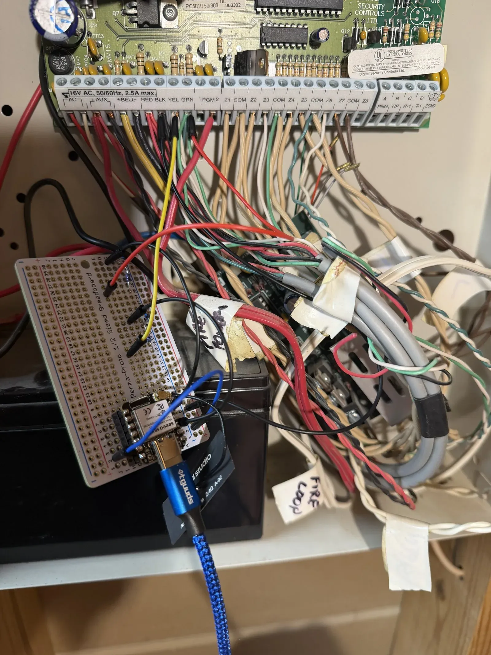
There is now a live dashboard showing every door, window, and motion sensor in the building, plus the alarm panel's AC power, battery, and trouble status, with history graphed in Grafana. The sensors are not new. They are the same wired contacts a security installer stapled into the walls in the late 1990s. The new part is a seven dollar microcontroller, four resistors, a shared ground wire, and one evening of work, all reading a bus the panel has been broadcasting on continuously for a quarter century.
It started with a chirping battery
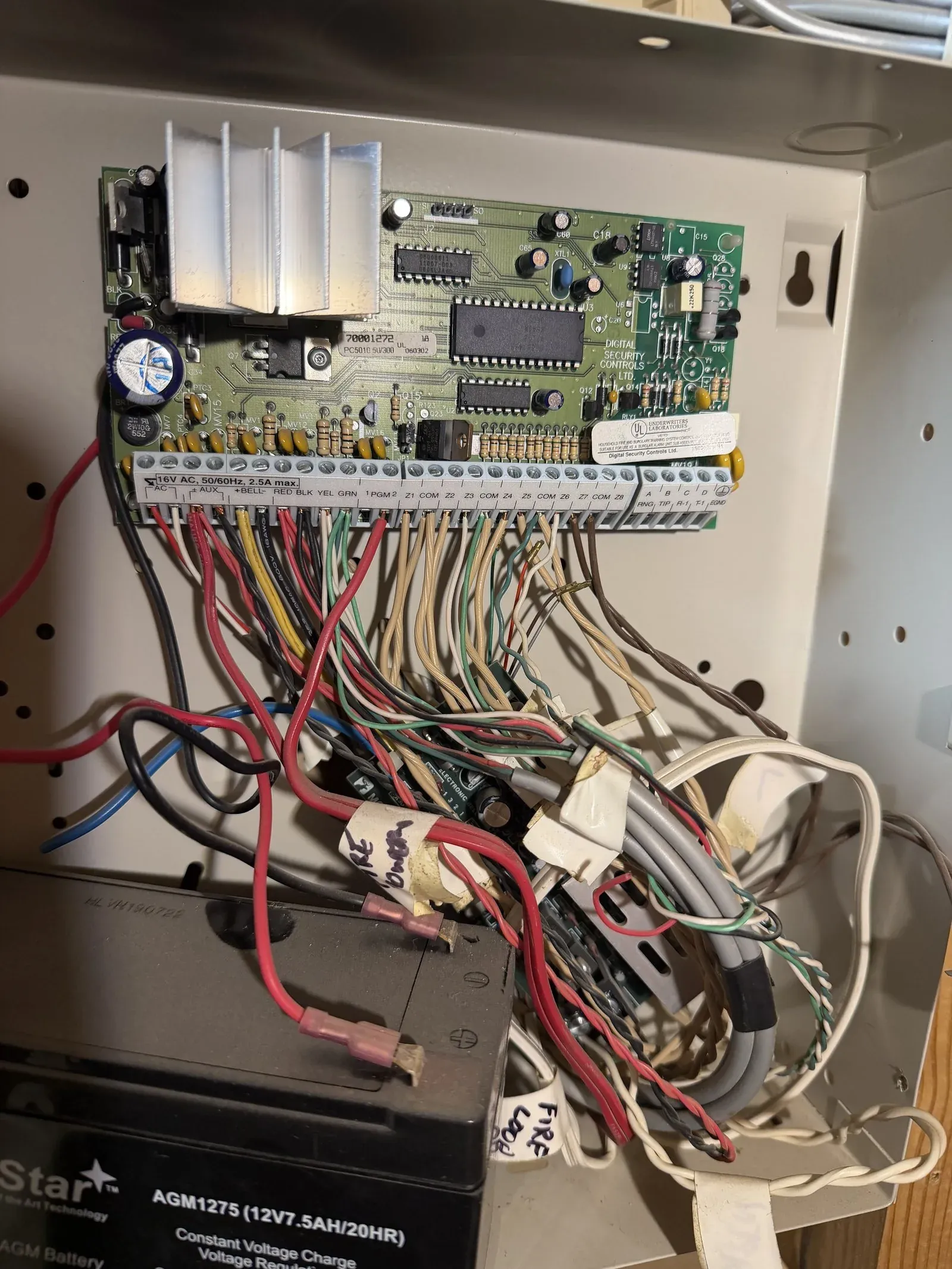
The panel is a DSC PowerSeries, PC5010 era, living in a grey metal can with a keypad out front. It had started chirping about a dying backup battery, so I opened the can to swap the battery and make it stop. Inside the lid sits a green circuit board with a long screw-terminal strip along the bottom edge, and a four-wire bundle running off to the keypads. The terminals are labeled RED, BLK, YEL, GRN. The manual calls this the Keybus.
That got my attention. This box has known the state of every door and window in the building for 25 years. It reports to a keypad on the wall and to nothing else. I wanted to know if I could read it.
What the Keybus is
DSC PowerSeries panels talk to their keypads over a simple four-wire bus. RED is +12V power, BLACK is ground, YELLOW is clock, GREEN is data. It is a clocked serial bus with the panel as the master, and the panel drives it continuously. Zone status, partition status, and panel health go out on the bus whether anything is happening or not. A keypad is just a subscriber.
The protocol was reverse-engineered by the community years ago, and the most usable packaging of that work today is the ESPHome dsc_alarm_panel external component, the Dilbert66/taligair lineage. That means no protocol archaeology is required. The decoder already exists. The remaining job is a safe electrical tap and a config file.
The tap, read only
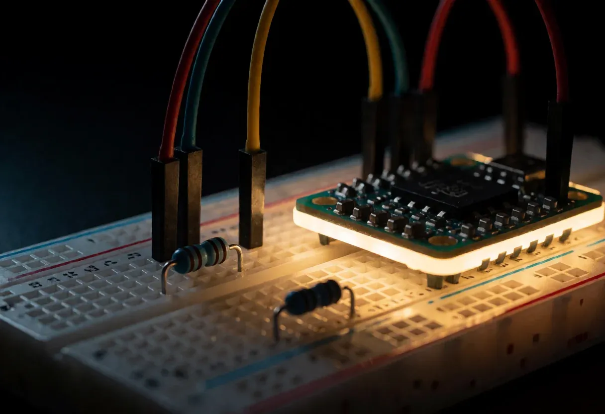
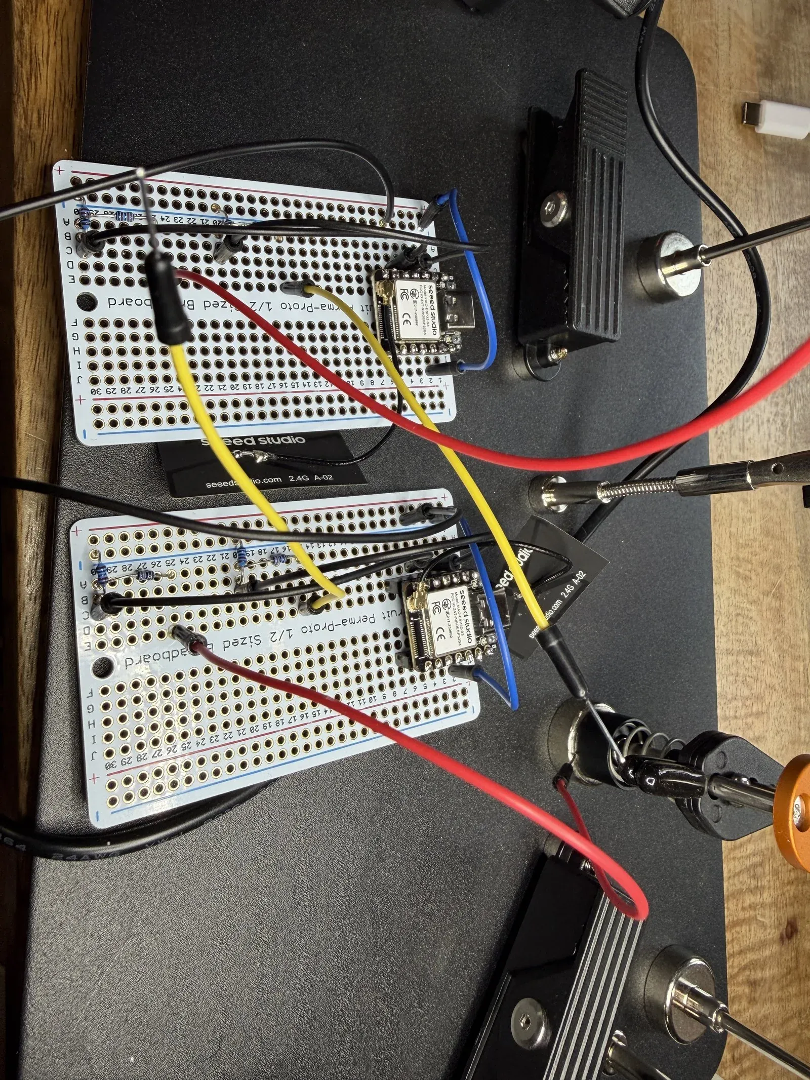
Keybus logic swings at roughly 12 to 13 volts. A 3.3V microcontroller pin does not survive that, so each signal line gets a resistor voltage divider: 33k from the bus line into the GPIO, 10k from that junction down to ground. That puts about 2.9V on the pin at bus-high, comfortably inside spec. Build two of them, one for YELLOW and one for GREEN, and run a third wire from BLACK to the board's ground so everything shares a reference. That is the entire interface. Four resistors and three wires.
The other half of safe is that this tap is strictly read only. Nothing on the microcontroller side ever drives the bus. The dsc_alarm_panel component supports writing (it can emulate a keypad and arm or disarm the system), and in this build that write pin is deliberately disabled in the firmware. The panel cannot tell the listener exists, and the alarm system keeps doing its job exactly as it did before. For a device whose whole purpose is to be trustworthy, passive is the right posture.
The brain
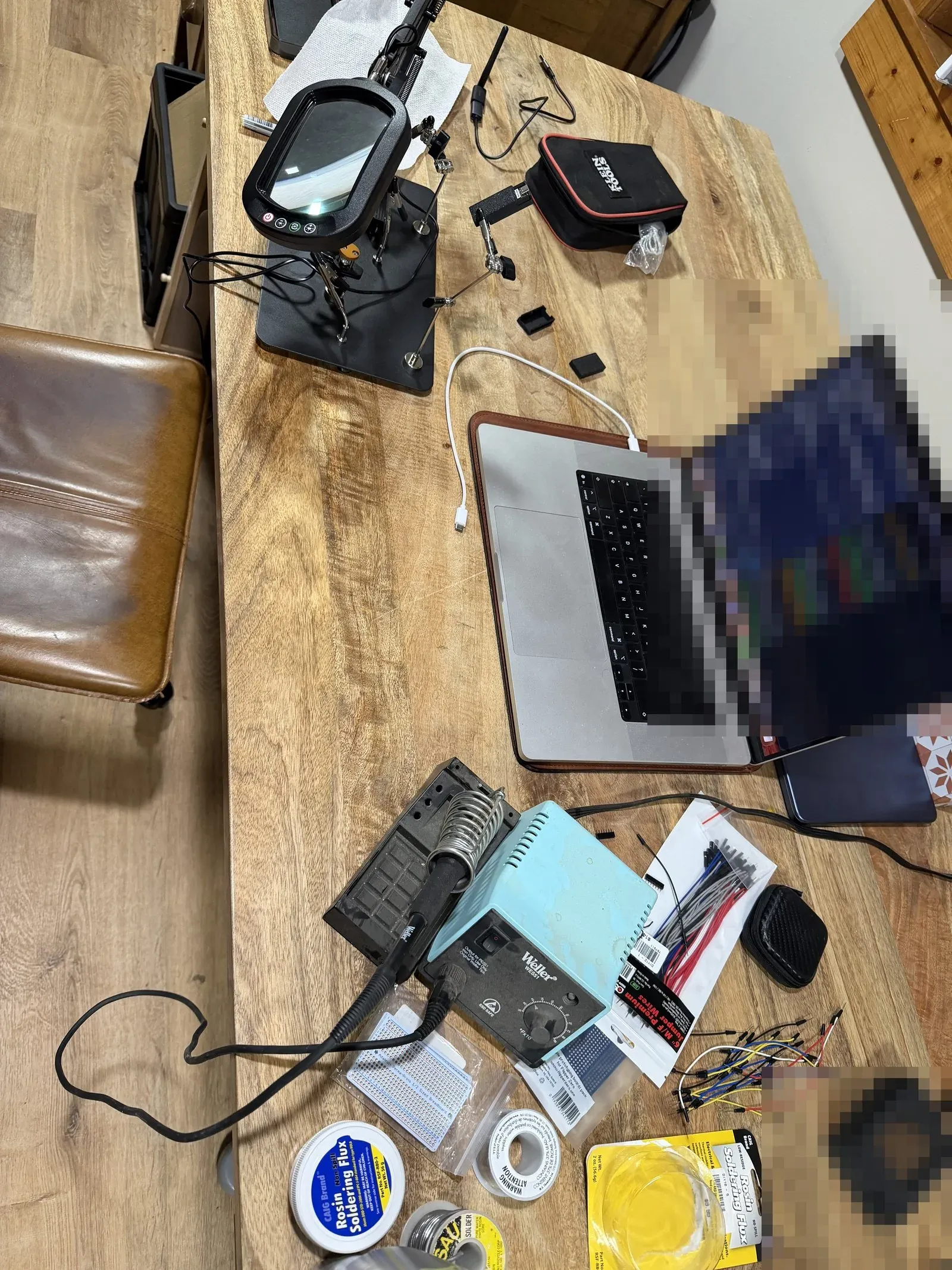
The board is a Seeed Studio XIAO ESP32-S3, about seven dollars, soldered to a small proto board with the dividers. It runs ESPHome with the external component and a short config: a clock pin, a data pin, write disabled. From the raw bus traffic it decodes each zone as open or closed, the partition state (ready, armed, alarm), and panel health (AC power present, battery condition, trouble flags).
One board-specific note. The GPIO numbers commonly shown in the component's examples did nothing on this board, and failed silently at that. Moving the dividers to GPIO4 and GPIO5 made it decode. If the log stays empty, try different pins before you doubt the wiring.
A meter proves connectivity, not signal integrity
The first board I wired up passed every bench check. Continuity was perfect, both dividers measured exactly right, the supply was clean. On the live bus, the clock came in garbled and the component could not lock on. I moved the same wiring to the second board and it decoded cleanly on the first boot, which pinned the fault to the first board itself.
The lesson is worth keeping. A multimeter proves DC connectivity and resistance. It says nothing about how a pin behaves on a fast edge. When a board reads perfectly on the bench but fails on a live bus, stop taking more measurements and swap the whole board. It is the fastest way to isolate the variable, and boards this cheap exist to be swapped.
A quiet building looks like a dead reader
The second trap is interpretive rather than electrical. Once the tap is running, the event log goes quiet, because nothing in the building is changing state. That silence is easy to misread as a dead reader. It is not. The panel's broadcast is a constant heartbeat, and the bus is fully alive even when every zone has been closed for hours.
The real test is to generate one event. Walk over, open a door, and watch for the single zone-open message. If that arrives, the whole chain works. Staring at an idle log tells you nothing either way.
Powering it permanently
For the permanent install the board should run off the panel itself, and the panel is happy to oblige. The AUX terminal supplies fused 12V intended for powered peripherals like motion detectors, and there is headroom to spare for an ESP32. The board wants 5V, so a small buck converter sits in between.
Do this in strict order. Wire the buck to AUX alone, set its output to 5.0V with a meter, and confirm which terminals are input and which are output. Only then connect the board. A buck that is mis-set or wired backwards will put 12V onto the 5V pin and destroy the board faster than you can react. I own one dead ESP32 that proves exactly how fast.
The payoff
ESPHome hands the decoded state out two ways. Its native API feeds Home Assistant, where every zone appears as a binary sensor. Front Door, Office Window, Motion, each one a live tile that flips within a second of the physical event, alongside the partition state and panel health. ESPHome also serves a Prometheus metrics endpoint, so Prometheus scrapes the same state on an interval and Grafana graphs it. That adds the dimension the keypad never had. History. Which doors actually get used, when the motion sensors fire, whether the panel ever loses AC, all of it queryable weeks back.
The full bill of materials:
- Seeed Studio XIAO ESP32-S3, about $7
- Two 33k and two 10k resistors
- A small buck converter, about $2
- Proto board, headers, hookup wire
- ESPHome with the
dsc_alarm_panelexternal component, write disabled - Home Assistant, and optionally Prometheus plus Grafana for history
The panel itself never changed. It has been broadcasting all of this on four wires since the late 1990s, decades before anyone called a door contact an IoT device. It just needed something other than a keypad to listen.
Comments
// Comments are reviewed before appearing. No spam. No noise.